Maurius, ZR6YY
Issue, 56 February 1998
 The Driven
elements of the ZR6YY antenna
Having received numerous requests to publish the design for the ZR6YY yagi I have now put the information out world wide in the hope that the design works for you.
Element Lengths |
|
reflector |
320 cm |
driven 1 |
296.5 cm |
driven 2 |
274.5 cm |
director 1 |
255 cm |
director 2 |
254 cm |
director 3 |
245 cm |
Element Spacing |
|
The measurements are taken from the reflector element |
|
reflector |
0 |
driven 1 |
78.5 cm |
driven 2 |
120.8 cm |
director 1 |
179.2 cm |
director 2 |
267 cm |
director 3 |
383 cm |
Construction
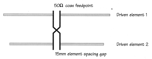
All the elements are isolated from the boom. The two driven elements are fed direct and 180 degrees out of phase. Feed the antenna directly with 50 ohm coax no balun necessary. Driven element 1 and driven element 2 are made up of two pieces of aluminium each separated by a 15mm gap.
Technical note from Clive, G4FVP
The design shown has considerable experimental potential and should give a good forward gain on a short boom length of only 3.83 metres. The concept of the yagi is the two driven elements which act as an end-fire array. This should theoretically give a gain of 3dB but will in practice be less. Remember to reverse the feedline between the two driven elements to ensure they are 180 degrees out of phase.
Maurius does not specify the feeder between the two driven elements however a starting point would be to use an electrical half wave length of 300 ohm slotted ribbon feeder. To determine the electrical half wave multiply the free space length by the velocity factor of the cable in use. For 300 ohm slotted ribbon feeder this will be 150/f X 0.87. For 50.100MHz this is 2.60 metres.