In December 1998 I started to experiment with a homemade three-element crossed yagi in an X-layout. The antenna was temporarily installed at about five metres above ground level, with 75/300-ohm baluns, dual coax feeders (75-ohm sat coax cable for economic reasons) of equal length and a homebrew `phasing and matching' switch box. The basic design originated from the `VHF-UHF Manual' edited by G6JP with all the phasing lines modified for 50 MHz (note: the hard part to find was the three-pole, six-position switch with ceramic wafers).
The switch box was built and tested with the feedlines terminated with two 75/300-ohm baluns and with terminating resistors. All low power VSWR measurements were well within 1:1.7; not bad for a start; especially soldering all the coax cables to the changeover switch (do you know how it feels like to handle six large octopuses in a small box…?).
Now back to six metres: with two types of antenna a reasonable comparison could be made. A homebrew six-over-six antenna with six metres spacing at 16 m above ground provided gain but also a lot of interference from two strong band I, channel 2 TV transmitters: one due east and the other one to the south-west, at approximately 70 miles. The S-meter reading averaged S9 + 30/40 with 40 dB attenuation.
The 3 element X-yagi had almost no gain but with the selection of 135°/45°/hor/vert/circ R/H + circ L/H I could eliminate strong TV/video interference and improve the signal to background noise ratio.
Happy with the first results, I worked on a four-element X-yagi with a longer boom with even better results. But how would such an antenna work at about 16 m (50') above ground level? This idea started a new process, since both experimental antennas were made from unused or second-hand TV + FM antennas. At this time, Peter (HB9RUZ) got involved and provided me with the needed antenna calculation and electrical engineering support (including a lot of head scratching and a happy local wine merchant…).
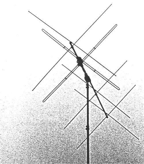
An excellent source for MIL-spec antennas (originally manufactured by WIPIC AG, CH-8163 Rümlang/Switzerland) was found at a Swiss army surplus sale. However, a redesign was necessary since the operating frequency range was 65 - 85 MHz. The new X-yagi uses a five-metre (~15') boom, dual equal-length 75-ohm coax feeders, matching baluns and a lightning arrestor. Folded dipoles are used with a grounded centre to reduce static noise.
After several modifications and design / layout changes, the X-yagi was finally ready to go on top of the free-standing tower, about 3.5 m above a three-element HF beam and at about 17 m agl. To the disadvantage of the X-yagi, the feed line is about twice the length of the feed for the six-over-six.

The four-element X-yagi on the top of the tower.
Now… is it worth? I think yes, firstly so that I have the legally required
polarisation and secondly because for this specific location I am able to reduce the
TV interference to a minimum or eliminate it totally (as observed with `Spectran').
The X-yagi does not have the gain, but it offers all the alternatives to adapt to the
incoming polarisations. It can be as dramatic as to change an S 3-5 signal to
no signal. For a comparison use a steady signal such as a beacon etc. since
QSOs are very short in duration.
So, which polarisation is the right one? It is comparable to a menu in a restaurant; the more choices you have, the more difficult it gets. After a few months of operation with this new toy I am unable to produce a clear answer, but there are indications that:
• Es signals tend to be R/H circular, L/H circular or vertical;
• long-DX signals have a tendency for R/H circular / 45°/ hor / vert for best signal-to-noise ratio.
• 135° seems to be the least used mode, but a station from Cyprus (5B/G1JJE) gave the best results in 135° for best S/N ratio.
Another interesting fact is that to do with the electrostatic noise (QRN) which is created by rain and snow: a 20-30 dB difference was observed on several occasions between the `noisy' six-over-six and the X-yagi.
In May 2001 a further modification was added to control/change the elevation angle, but I have not collected sufficient details/reports yet. It would be interesting to hear whether anyone else has experimented with this sort of antenna on 50 MHz and what the results were.
In order to keep the neighbours happy (at least sort of) I have constructed a dual-cavity band pass filter in line with a low-pass filter. Cavity size: diameter 120 mm, length 1500 mm, tuneable for frequency and input/output matching. All coax cables are double-shielded.