October 1992 Six News
By PA2HJS - UK6MG #887
 The
original antenna uses a hairpin type of feed to match it to 50
Ohms. The (asymmetrical) coax is connected directly to the driven
element, without any matching network to match the symmetrical
dipole to the asymmetrical coax.
The result is that the coax cable which feeds the antenna radiates a part of the energy instead of putting it into the aerial. Measurements showed that the gain of the original antenna was about 3 db short of the computer calculated gain.
 By changing the impedance of the driven element to
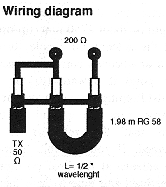
200 Ohms, it is possible to use a 1:4 halfwave balun to match the
antenna properly and to make sure that the symmetry is also
properly taken care of. a second measurement, taken after the
modification, confirmed that there was a marked improvement and
the gain is now in the magnitude of the calculated figure of 7 db
referred to a dipole (dBd). The hairpin feed was computer
modelled for optimum
performance (TNX PA2VST for the calculation).
The modified Tonna was used for HB0/PA3EUI (1991) and GU/PA2HJS (1992) and worked FB.
Here are the steps to take:
Remove the hairpin parallel to the driven element.
 Drill
holes in the bottom of the connecting box for the hairpin and the
RG58 balun coax, at the side opposite to the one where the feeder
coax comes in.
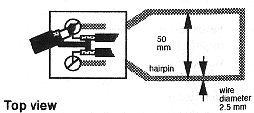
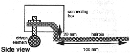
Make a hairpin from 2.5 mm thick copper wire with the dimensions as shown on the drawing, leaving the ends straight to be able to pass them through the two holes. Bend the ends to a round shape to be able to mount the hairpin under the nuts where the feeder coax used to be fixed.
Make a RG58 balun of 1.98 m length and fix it along the boom
of the antenna. I soldered the inner conductors on the hairpin
wires after they were fixed. Use a thick wire (the RG58 coax
braid will do fine) to connect the coax grounds
Shorten the driven element to a length of about 2750 mm
(tip-tip!)
 Put the
antenna on a pole, broom-stick or whatever convenient means and
point it upward (to the sky) whilst keeping it roughly one or two
metres from the ground to make sure that the reflector is not
detuned. If you are able to mount the antenna at the final
position on your mast and tune it there then do so (In most cases
this is very time consuming). After putting things together you
should have a reasonable match. If not, check the complete
system.
The antenna should be tuned by shortening the length of the driven element. With my aerial it tuned at the length of 2700 mm with a VSWR of 1:1 at 50.100 MHz. It matches well between 50.0 and 50.5 MHz.
If in doubt, do not hesitate to contact me.73 / GL!
Henk Schanssema, PA2HJS
e-mail: hjs@telesupport.nl
![]()