by Ken Willis, G8VR
Note: This article was updated in November 1999
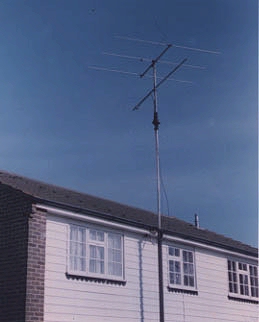 I wrote an article under the above heading in the Spring of 1989 and it
appeared in Practical Wireless in July of that year. In a later edition some further notes
were published, following some computer simulation studies on the antenna by Dr. Ian
White, G3SEK and my good friend Bob Reif, W1XP. Since then, several of these antennas have
been duplicated around the world, and from time to time I still receive enquiries from
potential builders. Consequently the editor of Six News suggested that it would be a good
idea to prepare an updated article, now that some six or seven years of operational
experience using this little antenna have shown its capabilities. We are indebted to the
editor of Practical Wireless who readily gave permission for some of the original text and
art work to be reproduced here.
There is little doubt that the most important part of any amateur radio
station is the antenna system, yet few of us are fortunate enough to live in areas where
tall masts supporting the sort of arrays we would like to use would be tolerated. The
release of 50MHz facilities posed antenna problems for many amateurs, particularly those
who previously operated only on the VHF/UHF bands where element and boom lengths are less
conspicuous, being more in keeping with typical domestic TV aerial systems. In the early
days of Cycle 22 , I commenced a study of the literature in an attempt to find a really
compact antenna, with forward gain, for six metres. From the outset there was no escaping
the fact that a compromise solution would be necessary.
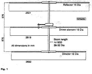 Figure 1.
My thinking was that as the solar cycle progressed the real DX would be arriving via F2 propagation, so I favoured a small yagi which should offer low-angle radiation, reasonable directivity and suitable front-to back characteristics, useful for reducing interference. Some early arithmetic soon indicated the problems. A 50MHz 5-element yagi with elements spaced 0.25 wavelength would require a boom length of almost 20 feet, definitely a non-starter at my QTH. Reducing the spacing to 0.2 wavelength still resulted in a boom length of almost 15 feet, which coupled with element lengths of the order of nine feet was again larger than I was prepared to contemplate and risk disturbing the excellent rapport with neighbours which I enjoy.
Eventually I found a reference to a small 3-element yagi designed for 50MHz portable operation by Ed Tilton, W1HDQ who was for some years the ARRL VHF editor and one of the operators involved in the first transatlantic six metre contacts with G6DH way back in 1946. Using his antenna as a starting point, I eventually came up with the small yagi described here; its dimensions and the matching system which I finally settled on are shown in
In my original article all the dimensions were given in inches, but in the Practical Wireless figures, reproduced here, they were converted to the metric system. Obviously some discretion is needed here, since, for example, a driven element shown as 2819 millimeters in length suggests the need for an accuracy of nearly one part in three thousand which is certainly not the case! Using a pocket calculator to divide the millimetric lengths given in the figures by 25.4 will give a close enough length for those like me who prefer to work in inches. I aimed at an antenna resonant close to 50.110MHz , for obvious reasons, and the dimensions given reflect this but before you take a hacksaw to metal, read the update paragraph later.
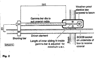 Figure 2
The great attraction of this little antenna is that its boom length is
less than six feet. The design is an example of what used to be known as a "plumber's
delight". This descriptive name arose from the fact that in this type of antenna, the
boom and all elements are bolted together with no form of insulation between them, so
standard plumbing parts such as T-junctions can readily be used to simplify the
construction. In my design, instead of using plumbing parts I chose clamps of the type
sold for securing car exhaust systems. These are readily available in various sizes from
automobile accessory stores. The U-bolt part of these should be a snug fit around the tube
selected for the boom. A short length of mild steel tubing (brass might weather better) is
welded (brazed) to the clip supplied with the U-bolt as shown in Figure 4. [Please
note that the spacing between the gamma match and the driven element should be 58.5mm NOT
23mm.]
The internal diameter of these tubes should be just large enough to admit the yagi
elements in a nice sliding fit. A single self-tapping screw through the outer tube and
biting into the element beneath enables the element to be centred on the boom and prevents
sideways movement. Figure 3 shows the dimensions and construction of the shorting bar
which is not at all critical, but preferably should be fairly "hefty" to reduce
inductance. As for the three yagi elements, provided they are not of the extremely narrow
type, their diameter is also not critical. In my prototype I used half-inch outside
diameter tubing.
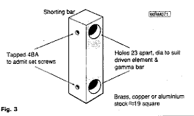 Figure
3
For efficient operation a good match between antenna and feeder is
paramount. With commercially built antennas there is usually little one can do but to
accept what is offered and hope for a good SWR, but with a home-brew antenna things are
more flexible. Over the years I have always favoured the gamma match, for not only is it
capable of providing an excellent match with the minimum of problems, it is also
particularly suited to the "plumber's delight" design because it does not
require the driven element to be cut in halves for a central connection to a feedline. For
those not conversant with the system, a gamma match consists of a short bar (the gamma
bar) running parallel to and off-set from one side of the driven element which is an
unbroken length of conductor. The end of the gamma bar furthest from the boom is connected
to the driven element by a shorting bar (Figure 2). The outer (braid) of the co-axial feed
line from the transceiver is then connected to the centre of the driven element boom),
while the inner conductor, via a suitable capacitor, goes to the open end of the gamma
bar. The length and diameter of the gamma bar and its spacing from the driven element are
not at all critical, but for any given arrangement there will be an optimum value of
capacitor to achieve a match. A problem has been finding a good quality capacitor of just
the right value which can be mounted near the centre of the driven element where it risks
being exposed to worst of the weather.
In this yagi the problem is overcome by making the capacitor a co-axial one, using a length of heavy duty coaxial cable with its outer copper braid stripped off, inserted into the tube which forms the gamma bar. (Figure 2).
Obviously the tubing and coax dimensions should be chosen to result in a good sliding fit, with little or no gap between them. By adjusting the length slid into the tubing, the capacity can be adjusted over a wide range. The dimensions shown in the figures are probably a good starting point for anyone wanting to duplicate this antenna.
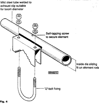 Figure 4.
They resulted in an almost unity SWR with my antenna. Some trial and error will usually be necessary to achieve a good match. I am fortunate in that my mast (which is camouflaged to look like a square drainpipe) can be cranked down to ground level very rapidly, so I was able to make several adjustments to the tubular capacitor to achieve the lowest SWR.Reference again to Figure 2 will show how I used a small plastic box mounted on the boom to provide a weatherproof anchorage for the various bits and pieces. A piece of sheet brass was cut to fit inside the bottom of the box , forming a mounting plate for a SO 239 socket bringing the feed line up from the transceiver. Self tapping screws through the brass sheet secure the box to the boom , at the same time providing an electrical connection between the braid of the feed line and the centre of the driven element (which electrically is also the boom). The centre pin of the SO239 then forms a convenient anchor point for the free end of the gamma capacitor cable. This should all be clear from the figures. Make sure that in practice the SO239 socket and its associated plug are well and truly taped up to give protection from the weather.
Considering the small amount of aluminium in the air, this little antenna has produced outstanding results at my station. By the time Cycle 22 was in decline, I had qualified for DXCC with more than 110 countries worked on 50MHz and 3 G-firsts (V47, ZWØ and 4J). I was also surprised to be the first in the UK to hear K6QXY "off the moon" in the February 1993 50MHz EME tests, though I suspect this was aided by my QTH which favours ground reflections.
Following publication of the original article, Ian White, G3SEK, and Bob Reif, W1XP, both used my design to illustrate the use of the powerful computer program MININEC for modelling antennas. This showed the predicted performance was good at 50.2MHz, but it would be even better at 51.2MHz, witha forward gain of 5.7dB and the back/front ratio of some 14dB. The implication was that the element lengths I had chosen were too short by about 2%. (1MHz in 50MHz), so a 'quick fix' might be to increase element lengths by this amount and re-adjust the gamma match.
Another feature of MINNINEC is its ability to opimize an antenna design, and it suggested the following changes:-
Reflector - add 85 mm to length (about 3.3 inches)
Driven element - no change in length
Director - subtract 25 mm from length (about 1 inch)
Of more significance were the recommended element spacings for the optimized version, which were quite different, i.e. reflector/driven element 555mm (22 ins), driven element/director 1125mm (44.3 ins).
MININEC predicted these changes would increase forward gain from 5.7 to 6.0dB (hardly significant) but considerably improve radiation pattern to a front/back ratio of 31dB as opposed to the original 14dB.
If I was to make this antenna again, armed with the computer data, it would be sensible to adjust the element lengths to bring resonance closer to 50.110, though the effect on forward gain would be minimal.
I would consider changing the position of the elements on the boom, however. The existing front/back ratio appears adequate for my purposes, giving enough signal off the back to alert me that things might be happening in directions other than the one I am pointing at the time. Also, from the point of view of the centre of gravity of the antenna, I like having the driven element close to the mast-head which is where feed line arrives. Remember that computer figures are one thing, achieving maximum theoretical performance in practice is another.
If you decide to build one, whichever dimensions you choose, the result will be a compact, rugged antenna performing well. We would all like a bigger antenna, but when F2 is about, 50MHz behaves more like HF. Would you turn up your nose at a well-matched 3-element yagi on 14 or 28MHz?
From a reception standpoint, it must be admitted that the lower forward gain of this small antenna compared much larger arrays used by some of the "big guns" on 50 MHz was noticeable during some major openings when stations they were working in areas such as W7 and JA were a few dB down at my QTH, but I don't think I missed a lot and I had more than my share of the good things on offer. I see no reason for changing to a bigger antenna for Cycle 23.
Anyone wanting further information can catch me on packet, G8VR @ GB7YUH..