Issue 44 Six News, January 1995
By Peter, PA2VST
Since the permit days on 6 meters, many operators in The
Netherlands have had discussions about converters, transverters,
input circuits, selectivity and power. This is because most of
the permit holders made their own equipment for this fantastic
band.
I did also and still do operate with the same transverter I made
in March 1988. But I have changed the input circuit in the front
end a couple of times because the poor original design did not
perform too well.
First the selectivity was poor and later on, on some occasions,
the selectivity and noise figure were also poor. As an
experienced EME operator on 144MHz, I knew it was not easy to
design a front end with the mentioned areas giving maximum
performance. Now, after some time experimenting I have quite a
fine input circuit that performs well.
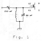
 Lets
have a look at some commonly used input circuits that often are
used in home construction or commercial designs (Figure 1.). The
advantage of this circuit is a good match to the antenna cable
and adjustable gain without unwanted oscillations. It is a fine
and stable amplifier. But, the antenna is loading the coil, so
the Q is rather low at this point and the selectivity is bad..
Signals much higher in frequency can easily break through the
150pF capacitor. In some cases the FET can be over driven and you
will find many birdies on the band.
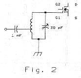
 A much
better solution is the circuit in figure 2. The low impedance of
the antenna cable is at a point on the coil at resonance, where
the impedance is more or less the same value. The antenna is thus
not degrading the Q and selectivity is much better. The gain is
good and the noise figure is what you would expect. With such a
design and a BF981 you can have a NF of 0.8dB. But, the match is
difficult to find. Look around 1.5 windings at the cold end of
the coil. It also depends on the coil quality itself. The 1nF
capacitor is not necessary but can be useful if a switching
circuit is part of the design. It will block DC. Near our
fantastic band we find, during all sorts of propagation, many
extremely strong signals that can simply pass the two previously
described circuits. So we need more selectivity but without
reducing our gain and increasing the NF. This is not easy. But
why do we not combine some well known circuits?
 We know
that a parallel LC circuit without load can have many good
qualities. We also know that we can change the impedance at any
one frequency of that LC circuit by changing the resonant
frequency (adjusting capacitor). This means we can have a good
match if we do not load the LC circuit (Figure 3.) If we connect
another parallel LC circuit in resonance at G1 of the FET and
don’t load it, you have fantastic selectivity, when the
correct C and L are chosen. When we couple these two LC circuits
in the same field, we are not loading the circuits too much, but
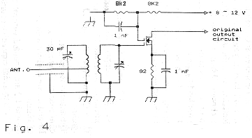
we do have fine low-loss coupling. The impedance of the FET is
high and the result is shown in Fig 4.
L1 + L2 are 8.5 winding 0.75 silverplated copper wire with a
diameter of 6mm. and 12mm. long.
C1 + C2 are 30pF trimmers of good quality.
The antenna is connected with thin 50 ohm coax at 1.5 windings.
L1 and L2 are coupled with a distance of 10mm.
L1 and L2 are mounted vertical onto the PCB to avoid capacitive
coupling.
 Experiments
and measurements show a better NF with approx. 0.6dB and a good
gain. Selectivity is also much improved and since the
installation of this input circuit I have not experienced any
first stage overdrive problems. The FET is a simple BF981. Henk
PA2HJS has also tried it with the same results. Having the same
gain, high selectivity and a good noise figure means also that
the match to the antenna cable is good. The connection to the
coil of the first LC circuit is not critical, but should not vary
more than one forth of a winding.
With this input circuit I can hear most of the available noise
sources (Sagittarius, Omega M17) and have heard K6MYC and K6QXY
off the moon. My antenna is a 1 wavelength, 5 element home-brew
yagi. I hope you can have the same performance in your receiver
as I have found.
All the best to all 6 metre operators, Peter PA2VST.
![]() To return to the archive page click here
To return to the archive page click here