by Brian Beezley, K6STI, Issue 39, October 1993
Here's a design for a 5-element beam on a 23-foot boom with an
unusual combination of performance characteristics. This Yagi
comes within 0.2dB of the maximum gain possible on the boom
length while keeping all back lobes 20dB down. This performance
combination is very rare. The trick was to optimise the design
over a narrow frequency range, 50.000 to 50.250MHz. Many 6-meter
beams, both homebrew and commercial, are designed to work to 51
or even 52MHz. These designs invariably sacrifice forward gain
and pattern quality for wide SWR bandwidth. When optimising a
design over a narrow bandwidth, fewer elements are needed. As
long as you have a certain minimum number, Yagi forward gain is
determined by boom length, not element count. Elements added to
the interior of this design won't increase its gain. (They may
increase the bandwidth over which the pattern and SWR remain
good, but this design adequately covers the low end of 6 meters.)
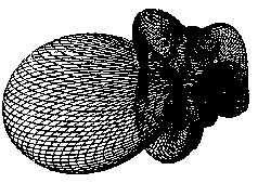
 Figure 1 - 3D plot - Peak 10.26 dBd @
50.110MHz
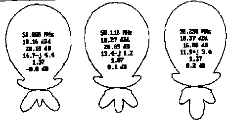
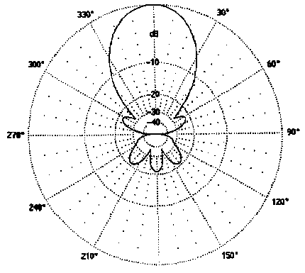
The free-space forward gain of this Yagi varies from 10.2 to 10.4dBd over 50.000 to 50.250MHz. These figures include conductivity losses of 0.08dB for 6061-T6 aluminium elements. When matched at 50.135MHz, SWR is less than 1.4 across the frequency range. The worst-case back lobe is 20dB down at 50.000, 21dB at 50.100, and rises to 16 dB at 50.250MHz. This design was simultaneously optimised for maximum forward gain, minimum worst case back lobes, and adequate and impedance. Conventional F/B was not optimised. This parameter takes the rear pattern into account at a single point.
The tuning of Yagi elements depends not only on their length
but also on diameter, diameter tapering, and mounting method.
These factors affect element self-impedance and thus alter
antenna response. Thinner elements, tapered elements, conductive
mounting brackets, and through-the-boom mounting shorten
effective element length. Design dimensions are given for
insulated, untapered, 0.375" diameter elements, for
insulated, untapered, 0.5" diameter elements, and for
elements with Cushcraft A50-6S tapering and mounting. If you use
different elements or mounting methods, you'll need to adjust
element lengths for optimum performance.
This design has a special property which makes it easy to adjust
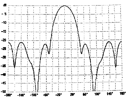
element tuning experimentally. The azimuth pattern has three back
lobes which are equal in amplitude only at 50.100 MHz. Since
rear-lobe amplitude changes rapidly with frequency, you can
easily verify that your antenna is correctly tuned. If the rear
lobe is larger than the other two back lobes, the effective
length of your elements is too long. If smaller, your elements
are too short. You can use this simple test to obtain correct
electrical behaviour for any physical element mounted by any
method. When adjusting parasitic-element lengths, make equal
changes to all parasitics. The input impedance of this design is
about 12.5 Ohms. You can use any matching method as long as you
observe the fundamental rule of Yagi matching: Never alter
parasitic-element lengths or spacings of an optimized design to
get a good match. Driven-element length has virtually no effect
on gain or pattern, so you're free to adjust this dimension when
matching. Don't after element spacing. Change parasitic-element
lengths only to move the equal-back lobe frequency to 50.100 MHz.
 Figure 2 - Polar Plots @ 50.088, 50.110, and
50.250MHz
When I built this antenna in 1989, I gamma-matched it. However, I wouldn't do this with the knowledge I have today. A gamma match can induce current on the shield of a coaxial feed line. It can also induce current in the boom unless the driven element is insulated. These stray currents can reduce forward gain and degrade the pattern. You may be lucky as I was and get away with gamma matching, but why take a chance? Use a hairpin, T-match, or folded dipole and a good balun. The 12.5 Ohm input impedance transforms to a feed impedance of 50 Ohms for an equal diameter folded dipole. You can feed the folded dipole directly with 50 Ohm coax if you use a current type balun. You can make one by slipping ferrite beads over the coax or you can simply coil the coax into a few turns near the feed point. This design was developed in 1989 but was not published for some time. A carefully constructed, untapered, insulated-element version of this design came out 220KHz low. (I had to DF cordless phones below the 6-meter band to find the equal-back lobe spot!) I thought that perhaps some obscure environmental factor was responsible for the discrepancy (like the conductivity or dielectric constant of my composition roof). In typical ham fashion, I simply cut a quarter inch off each element tip and used the beam successfully. But the 220-KHz anomaly continued to bother me. It wasn't until I began to use the sophisticated Numerical Electromagnetics Code (NEC) that I finally understood what was going on. NEC predicted that the antenna would perform as originally measured. The MININEC-calibrated algorithm I used to optimise this design had a built-in frequency offset! I immediately recalibrated all of my antenna-design programs to NEC. I subsequently found references to the MININEC frequency offset in the professional literature. If you optimise this Yagi for maximum forward gain without regard to pattern, impedance, bandwidth, construction tolerances, or reason, you can squeeze 0.2dB more out of the design. However, the back lobe degrades to just 11dB down and input impedance nose-dives below 5 Ohms. You say that you can match anything? That you never leave 50.110? That you don't experience rear-signal QRM on 6 meters, and that you want all the gain you can possibly get? What about those damn power leaks that always seem to start up from every direction whenever the band opens? What about the 3CO DXpedition which shows up on 50.300 and gets chased off the island before you're done retweaking your match up on the tower? If you're greedy about Yagi forward gain, you'll live to regret it.
 Figure
3 - Polar Plot - 50.110. 0dB = 10.26dBd
You can stack two of these Yagis for more gain. An H-plane
stacking distance of 27 feet provides 3.1dB additional gain in
free space. (Other stacking distances shift the equal-back lobe
frequency away from 50.100MHz and require element readjustments
However, unless the array is very high, you won't come close to
free-space stacking gain in practice. The elevation patterns of
Yagis at different heights don't combine favourably. For example,
adding a second Yagi 27 feet below one at 50 feet improves gain
less than 1.2 dB at elevation angles below 5 degrees. E-plane
stacking is an attractive alternative. If you space the booms 29
feet horizontally, you'll get 3.0dB gain over a single Yagi
regardless of height. The 3-dB beam width will be 9 degrees, with
deep nulls at 20 degrees and side lobes 9.4 dB down at 31
degrees. Before you go to the trouble of E-plane stacking, think
carefully about the operational inconvenience of such a narrow
main lobe. The cross boom must be non-conducting near the Yagis.
If you'll settle for an improvement of 2.6dB, the 8-element Yagi
listed below is much more manageable than a side-by-side pair of
5-element designs. To give you idea of how this Yagi compares
with other designs, tables 1 and 2 show some NEC results at
50.110 MHz:
 Figure 4 -
Polar Plot - 50.110MHz
A50-5S, A50-6S, and 617-6B are wide-band Cushcraft designs. 6M2WL and 6M2.5WL are M2 Enterprises designs. NBS-5 and NBS-6 are National Bureau of Standards designs empirically optimised for maximum forward gain. Five is the subject of this article, while Four, Six, Seven, and Eight are other computer optimised, narrow-band designs. Gain figure-of-merit is antenna gain minus maximum practical gain (maximum gain for the boom-length with reasonable input impedance and bandwidth, a definition which is vague but which can be evaluated mathematically as a function of boom length). As N6ND says, for a really good signal you need dBs in the air and dBs on the desk. This simple Yagi design will take care of airborne dBs. Desktop dBs are a matter between you, your licensing authority, and your spirit of adventure.
Element Postitions and half lengths for Optimised 5-element Yagi (inches)
| Position | E1-#1 | E1-#2 | E1-#3 |
| 0.00 | 57.54 | 57.42 | 58.43 |
| 44.06 | 54.85 | 54.59 | 55.39 |
| 107.89 | 53.48 | 53.16 | 53.88 |
| 194.86 | 52.59 | 52.23 | 52.89 |
| 270.62 | 52.59 | 52.24 | 52.90 |
El #1: 0.375" diameter, non-conductive mounting bracket
EI #2: 0.5" diameter, non-conductive mounting bracket.
El #3: Cushcraft A50-6S element mount 24" half-length of
0.75" diam., 0.625" diam. tips, U-bolt mount
Half-lengths are lengths measured from the centre of the boom to
the element tip.
![]() To return to the archive page click here
To return to the archive page click here