 |
The 6 Metre Beacon Project by Lawrence D. Woolf, BA(Hons), BSc, Dip.Math(Open), GJ3RAX Published on the UKSMG web site with permission of the Radio |
|
The 6 Metre Beacon Project by Lawrence D. Woolf, BA(Hons), BSc, Dip.Math(Open), GJ3RAX Published on the UKSMG web site with permission of the Radio |
A few years ago I was asked, by Geoff GJ4ICD, to help design and make some beacons for the 6 metre band. These were to be sent to various parts of the world which were not covered by existing beacons. My part was to work on the exciter and the keyer, while Geoff would add the amplifiers.
These units were to be assembled on printed circuit boards that would be easy to work on, if necessary, at their destinations. This meant that the keyer matrix should use diodes that could easily be changed if a different callsign or grid locator was required. The size would be larger than for an EPROM design, but this did not matter. If a unit with an EPROM had to be re-programmed then a return to base would be much more likely.
The exciter was designed for frequency shift keying so the choice of crystals was nominally 12.5 MHz and doubled twice. This required the use of parallel resonance crystals, oscillating at their fundamental frequencies, which could easily be trimmed on to the required frequency and then shifted, by about 1 kHz, by the keyer. It would have been possible to choose series resonant harmonic crystals to oscillate directly at the output frequency within the 6 metre band. Adjustment and shifting would not have been easy so this was not considered practical.
The keyer circuit
The keyer, Fig 1, was based on six, commonly available, integrated circuits. IC1 is a CMOS CD4049B hex inverter which is used as the clock oscillator and a tone oscillator, for testing. IC2 and IC3 are TTL dividers, type 74LS93. The 74LS versions were chosen for their low power consumption. Each of these divides by sixteen and drive the matrix scanners, IC4 and IC5. IC4 is a 74LS154 which is a 4-line to 16-line decoder and drives the diode matrix. IC5 is a 74150 data selector which selects one of the 16 output lines from the diode matrix. This device was a standard TTL IC as I could not find the low power version at the time. IC6 is a 7805 voltage regulator which accepts the 12 Volt supply line and provides the 5 Volts that must be used for the TTL devices. The only discrete transistor is TR1, a BC548, which is used as a switch to key the exciter.
The frequency of the clock oscillator is set by R2 and C1 and has been chosen to provide a keying speed of about 8 words per minute. The frequency of the tone oscillator is set by R6 and C2 to a little under 1 kHz. In both cases the frequency of oscillation may be calculated from f(Hz) = 1/(2.2RC). The tone oscillator is only used for testing and is suitable for driving a high impedance load, such as a ceramic transducer. As the tone oscillator is driven from the output of a TTL device which varies slightly in output voltage, the tone frequency warbles a bit so should not be used for any other purpose. The main output from the keyer is from the collector of the switching transistor, TR1, at O/P 2 and this is used to key the exciter. The output from this stage is normally at logic low and goes to the high state when a diode is scanned. An alternative inverted output point, O/P 1, is given for other purposes but has not been used for the beacons.
IC4 and IC5 scan through the diode matrix, selecting one location at a time. There are 256 possible locations of which about 80 will typically have diodes fitted. This varies with the Morse encoding of the callsign and grid locator. Each diode causes a tone, or frequency shift, at the dot rate so one diode is required for a dot and three for a dash. These two ICs and all the matrix diodes could have been replaced by an EPROM but this system is much easier to change if needed with just a soldering iron and, perhaps, a few more diodes.
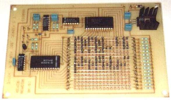
Fig 2 shows the matrix programmed with my callsign and grid locator. The callsign is scanned in the sequence A1, A2, A3… A15, A16, B1, B2…through to E9. Other callsigns will take up more or less matrix space. In this case the grid locator runs from G1 to J13. This schematic layout shows each column being scanned from top to bottom in sequence. The chosen PCB layout is actually scanned in rows from left to right, rather like a TV raster.
When the keyer is first switched on the scan actually starts in the middle of the matrix. This is because IC2 and IC3 are connected in a slightly unconventional way with their inputs clocked at B rather than A, so that their output sequence is now B, C, D, A instead of A, B, C, D. This was purely to simplify the PCB layout and does not matter for continuous beacon use.
When supplied with 12 Volts the current consumption is typically 80 mA.
The exciter
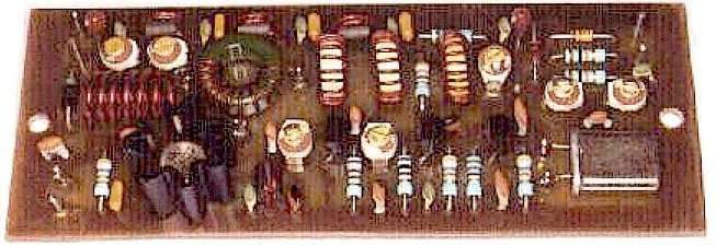
The exciter, Fig 3, uses three junction FETs and one bipolar transistor. The FETs are all J310s. The crystal oscillator, TR1, allows the crystal, XL1, to operate at its fundamental frequency, 12.5 MHz nominally, with the output of the stage tuned to the second harmonic at 25 MHz. Frequency shift keying is provided by the switching diode D1. In the keyed state the frequency is trimmed by C3 to about 1 kHz above the nominal output frequency. When the key I/P goes high, the unkeyed state, then D1 conducts and allows C2 to work in parallel with C3, lowering the frequency to the nominal. This allows a listening station to receive a continuous signal with the keying providing Morse code. An upper side-band receiver is tuned to zero beat the unkeyed signal. If the receiver has a narrow CW filter then, for identification, the higher frequency signal must be tuned in to ensure that "reversed code" is not listened to which can sometimes cause confusion.

TR2 is a doubler stage to the final frequency at around 50 MHz. TR3 is a grounded gate amplifier which drives the output stage, a 2N4427, to about 500 mW output. This is normally used to drive an external amplifier to about 10 Watts output.
The coils L1, L2, L4 and L7 are wound on toroidal cores. L9 is part of the low pass filter and is air-cored. If the final output were to be taken from this stage then a bit more filtering would be recommended. It has been assumed that additional filtering is provided in the external amplifier. The other inductors are all chokes wound on small ferrite beads.
For alignment I usually connect the output to a PM20 power meter, from Lake Electronics. This has a built in 50 Ohm load and reads up to 1 Watt on the lower range, with 20 Watts on the higher range. A 6 metre receiver is set to the expected output frequency. Adjusting C9 is usually enough to get the oscillator going with C2 and C3 setting the nominal frequency and shift. The other trimmers can then be tuned for maximum output. As this unit is run continuously it is most important to adjust it for minimum unwanted signals. The only easy way is to use a Spectrum Analyser so that all outputs can be seen at the same time. I use the Simple Spectrum Analyser that was published in Radio Communication, November 1989, by G4PMK.
When supplied with 12 Volts the current consumption is typically 140 mA.
This exciter could easily be adapted for FM or CW use on 6 metres or, with a few more changes to the tuned circuits and crystal, even on 4 metres. For FM the diode D1, used for keying, could be replaced with a suitably biased variable capacity diode. For CW either the oscillator or a later stage could be keyed.
Components
Most of the components were obtained from Cirkit, Farnell and RS Components.
The heatsink shown on the prototype exciter PA transistor, TR4, was RS 401-548 but was later considered not ideal for continuous use. As the PCB was fitted in a diecast box, Eddystone 7134P, later units used RS 401-784 heatsinks which were bolted to the box.
The heatsink used on the keyer regulator, IC6, was RS 401-964. No significant temperature rise is normally found so this is probably not strictly necessary at normal ambient temperatures. As some of the beacons would be sent to hot climates it was considered safer to include it.
The resistors used are Philips SFR25 which are metal film, 5% tolerance and rated at 0.4 Watts.
The small fixed capacitors are Philips miniature ceramic plate devices which have good RF characteristics. The larger values, mostly used for decoupling, are monolithic multilayer types or tantalum.
| C1 | 1 nF | R1 | 10 k | |||
| C2 | 30 pF Trimmer | R2 | 10 k | |||
| C3 | 30 pF Trimmer | R3 | 47 k | |||
| C4 | 22 pF | R4 | 560 | |||
| C5 | 100 pF | R5 | 560 | |||
| C6 | 100 pF | R6 | 47 k | |||
| C7 | 1 nF | R7 | 100 | |||
| C8 | 10 uF Tant | R8 | 220 | |||
| C9 | 30 pF Trimmer | R9 | 4.7 | |||
| C10 | 22 pF | |||||
| C11 | 10 pF | D1 | 1N4148 | |||
| C12 | 1 nF | D2 | 6.8 V Zener | |||
| C13 | 1 nF | D3 | 1N4004 | |||
| C14 | 100 nF | |||||
| C15 | 30 pf Trimmer | TR1 | J310 | |||
| C16 | 22 pF | TR2 | J310 | |||
| C17 | 47 pF | TR3 | J310 | |||
| C18 | 1 nF | TR4 | 2N4427 | |||
| C19 | 100 nF | |||||
| C20 | 22 pF | XL1 | 12.5 MHz | (Nominal) | ||
| C21 | 30 pF Trimmer | |||||
| C22 | 10 pF | L1 | T37-6 | 15 Turns | ||
| C23 | 1 nF | L2 | T37-12 | 12 Turns | ||
| C24 | 100 nF | L3 | FX1115 | 3 Turns | ||
| C25 | 1 nF | L4 | T37-12 | 12 Turns | ||
| C26 | 100 nF | L5 | FX1115 | 3 Turns | ||
| C27 | 30 pF Trimmer | L6 | FX1115 | 3 Turns | ||
| C28 | 22 pF | L7 | T50-12 | 13 Turns | Tapped at 4 turns | |
| C29 | 30 pF Trimmer | L8 | FX1115 | 3 Turns | ||
| C30 | 22 pF | L9 | Air core | 6 Turns | 6 mm i.d. | |
| C31 | 22 pF | 12 mm long | ||||
| C32 | 68 pF | |||||
| C33 | 1 nF | Wire | L1 - L8 | 0.56 mm | ||
| C34 | 10 uF Tant | L9 | 1.0 mm |
| BK-01 Beacon Keyer | ||||
| C1 | 470 nF | D1 | 1N4148 | |
| C2 | 10 nF | D2 | 1N4002 | |
| C3 | 47 nF | |||
| C4 | 470 nF | IC1 | 4049B | |
| C5 | 470 nF | IC2 | 74LS93 | |
| C6 | 47 nF | IC3 | 74LS93 | |
| C7 | 47 nF | IC4 | 74LS154 | |
| IC5 | 74150 | |||
| R1 | 220 k | IC6 | 7805 | |
| R2 | 120k | |||
| R3 | 10 k | TR1 | BC548 | |
| R4 | 4.7 k | |||
| R5 | 1 k | Matrix diodes 1N4148 | ||
| R6 | 47 k | as required | ||
| R7 | 100 k | |||
| R8-R23 | 4.7 k | |||
| Note 1 |
| O/P 2 (TR1) is connected to Key I/P of BT-01 |
| Note 2 |
| Tone oscillator used for testing only |
| Note 3 |
| Keying speed is set by R2 and C1 |
Full size PCB layout (circuit side)
Full size PCB layout (component side)
Beacons
The beacons made so far have been,-
| Frequency, MHz | Callsign | Grid |
| 50.014 | 9M6SMC | OJ85AX |
| 50.035 | V31SMC | EK57MM |
| 50.052 | Z21SIX | KH52MK |
| 50.065 | GB3IOJ | IN89WE |
| 50.075 | JY6ZZ | KM71WX |
| 50.078 | OD5SIX | KM74 |
The only failure, so far, was V31SMC which was taken to Belize by G3SED and G4CVI. It was installed on high ground and, I have been told, was heard by many stations in the USA. During a storm there was a lightning strike which proved disastrous to it. It was eventually returned to Jersey and required a couple of transistors changing on the exciter board. Some of the wiring had melted insulation. Geoff was able to restore the PA unit which had also expired. The keyer had survived the ordeal.
The beacons 9M6SMC and V31SMC were financed and sponsored by SMC Ltd. The callsign 9M6SMC was doubly appropriate as it was located at the Sabah Medical Centre. The external amplifiers for the Z21SIX and OD5SIX beacons were donated by Nevada UK.
Any correspondence should go to Lawrence GJ3RAX and not the
UKSMG
![]() To return
to the Bits & Pieces page click here
To return
to the Bits & Pieces page click here